
Multimodal fNIRS-EEG measurements — Integration on the head
As mentioned in the introductory blog post of this series, there is limited space on the scalp that needs to be shared between fNIRS optodes and EEG electrodes in simultaneous fNIRS-EEG measurements. This co-placement of fNIRS and EEG should:
Allow proper coverage of the area of interest
Meet the technical demands of each technique
Minimize interference
In this blog post, we address these points in more detail, explaining why and how they are relevant.
EEG has a relatively low spatial resolution, and EEG electrodes are usually distributed over the scalp to achieve full brain coverage. In contrast, fNIRS has a relatively high spatial resolution, and it is common that researchers measure local activity only in the area of interest. There are standard systems, such as the 10-20 system (figure 1), that serves as a reference for EEG electrode placement. These systems use anatomical landmarks to specify positions for the electrodes according to the head size. This allows researchers to measure from, and compare across, equivalent scalp anatomical locations among different subjects. These locations can also be used as a guide for fNIRS optode placement.

Figure 1: Illustration of the 10-20 EEG international system for electrode placement. Taken from Strobbe, Gregor. (2015) Advanced forward models for EEG source imaging
Additionally, EEG channels measure the voltage difference between an electrode and a reference. This reference usually is the same for all electrodes, and it can be the average of all channels, the average of two earlobes, or a single electrode.
Conversely, each fNIRS channel measures the changes in light emitted from a transmitter into tissue and detected by a nearby receiver. This pair of optodes should be usually placed at 30 mm distance from each other to form a channel (figure 2). The inter-optode distance (IOD) will determine the depth of sensitivity and could vary depending on the type of channel (long/short), location, or age group.

Figure 2: Illustration of a fNIRS channel
We refer to the layout of optodes for measurement as an optode template. This template specifies the positions of transmitters and receivers in regard to each other to form measuring channels. The template is selected based on the size and shape of the target area.

Figure 3: Example of an optode template (Brite 24 channels). Blue and yellow dots represent receiver and transmitter respectively
For a simultaneous fNIRS-EEG measurement, fNIRS optodes and EEG electrodes are usually placed in the same headcap (figure 4B). It is possible to either place the electrodes in the fNIRS headcap or vice versa. However, we strongly recommend placing EEG electrodes in the Neoprene headcap provided within our fNIRS packages (figure 4A).
At Artinis we designed and developed our own neoprene headcaps with an ergonomic fit. The fabric absorbs external light and is sturdier, ensuring the optodes will not move. Some EEG electrodes easily fit in our headcap while others may need a holder or adapter.

Figure 4: A) Artinis neoprene headcap with EEG marking.
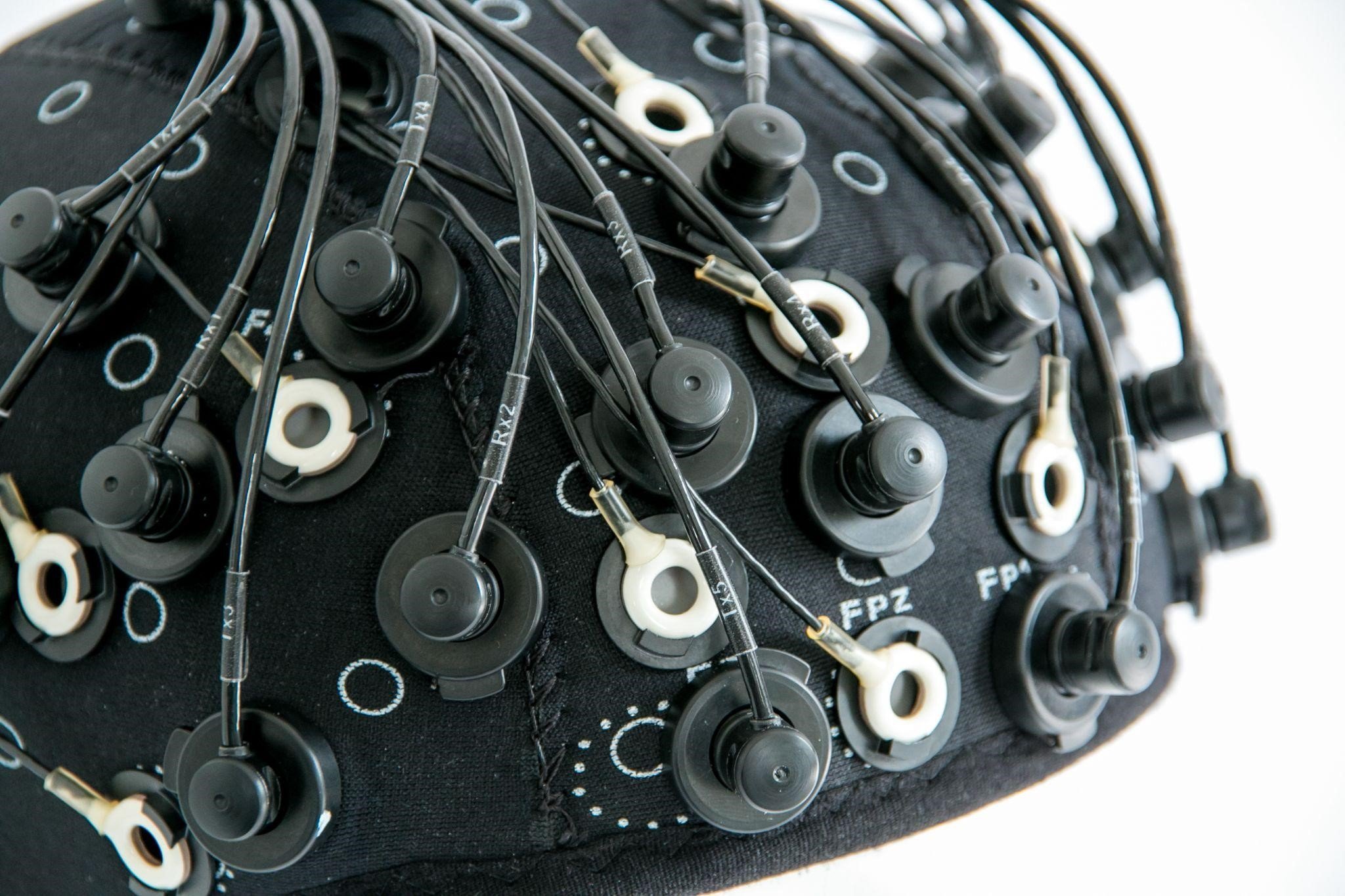
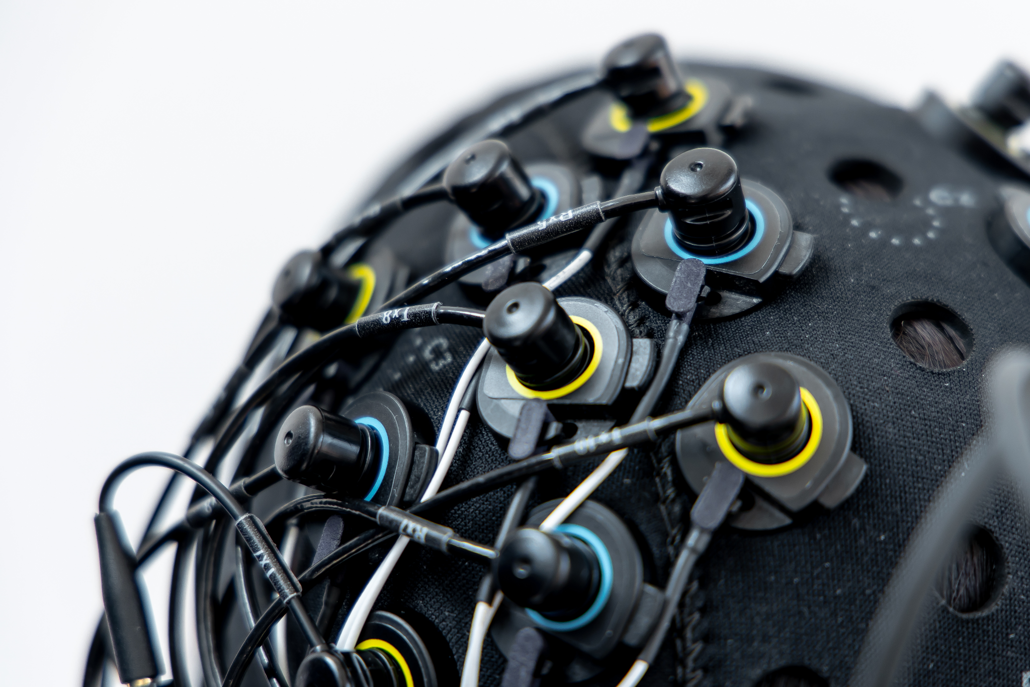
4 B) Placement of fNIRS optodes and EEG electrodes in separate holders in Artinis neoprene headcap. 4 C) Placement of fNIRS optodes and EEG electrodes in combined holders in Artinis neoprene cap.
Our headcaps are primarily designed for fNIRS measurements and hence have optode marks in a grid of ~ 30 mm. Additionally, EEG locations for the 10-20 system are also printed on the headcap which sometimes overlap with the 30 mm grid marks (figure 4A). Researchers usually prefer to place electrodes according to the EEG standard systems and place fNIRS optodes in between.
Please note that as mentioned above, the inter-optode distances should be kept at around 30 mm. Therefore, depending on the number of electrodes and their size, it might not be possible to fit a large optode template (figure 3) in between the electrodes. One solution could be using an alternative template composed of smaller sub-templates (figure 5). Another solution is reducing the number of EEG channels.

Figure 5: Example of an optode template with 4 groups or subtemplates (Brite 2x5+2x4)
The aforementioned solutions do not work in the case of high-density fNIRS-EEG measurements. The alternative solution for these studies is to use combined holders that can accommodate both EEG electrodes and fNIRS optodes (figure 4C). This solution is only available with certain EEG devices.
Lastly, it is worth mentioning that since fNIRS is an optical technique, interference from EEG is not expected. However, if the sensors are placed in proximity to each other, the electronics of the optodes can cause interference in EEG signals. This interference can be minimized by lowering the skin-electrode impedance, and with a low enough impedance it can be completely eliminated.
“Since fNIRS is an optical technique, interference from EEG is not expected.”
The approaches addressed in this blogpost are the most commonly used but there is always room for other possibilities and customized solutions. Contact us for more information.
Talk to us about your fNIRS - EEG setup!
We are happy to think along with you if you tell us about your research at askforinfo@artinis.com