
A guide on how to ideally apply an optode template using our (f)NIRS devices
Finding the correct optode template for your study can be a challenge, especially when using devices that offer a great choice of templates, such as the Brite. In this blogpost, we discuss what optode templates are, how the perfect optode template can be chosen and how they can be correctly applied to a headcap.
All of our NIRS and fNIRS devices come with two different types of optodes:
Transmitter(s): transmitting light with two different wavelengths into the tissue
Receiver(s): detecting the light that is scattered back to the surface by oxygenated and deoxygenated hemoglobin
A transmitter and a receiver can form a channel if they are placed in an appropriate distance (see Figure 1). The receiver then detects the light that is transmitted by the transmitter and scattered back to the surface of the tissue. As the transmitters of our devices fire asynchronously, one receiver can form channels with multiple transmitters.

Figure 1: Graphical outlay of a measurement channel. Optodes (yellow: transmitter, blue: receiver) placed on the surface of a tissue to measure relative concentration changes of oxygenated hemoglobin (O2Hb) and deoxygenated (HHb) hemoglobin
What is an optode template?
An optode template displays the configuration of transmitters and receivers that is used for a device in a measurement. Optode templates are needed in our software OxySoft to create correct measurement graphs. This configuration displays, e.g., how the optodes are placed on the headcap.
An example of an optode template for the Brite is shown in Figure 2. The yellow dots represent transmitters and the blue dots depict receivers. The line between both optodes with a white dot in the center represents one channel.

Figure 2: Optode template 27 channel for the Brite device
For some of our devices, multiple optodes templates are available. These templates can either consist of one big template, or be divided into multiple smaller sub-templates, to measure from different locations or with short separation channels. The names of the optode templates are indicative of the number of sub templates, channels and short separation channels (SSC) that the template has, respectively. An example of an outlay including sub-templates can be seen in Figure 3. This template consists of four different sub-templates, two of them forming five channels (group 1 and 4), two of them forming four channels (group 2 and 3).

Figure 3: Optode template 2x4 + 2x5 channel for the Brite device
Why do we have different optode templates?
Each of our NIRS and fNIRS devices comes with a set of optode templates that are tailored to the device, which is due to various reasons:
Our devices consist of different numbers of transmitters and receivers. For instance, the PortaMon contains three transmitters and one receiver, whereas the Brite offers 10 transmitters and 8 receivers. Therefore, the Brite offers increased flexibility in choosing options for optode template creation.
Our devices are optimized for use in different application fields. Accordingly, a specific arrangement is required to acquire certain measures. Whereas all devices can measure relative concentration changes of O2Hb and HHb using the Modified Lambert-Beer Law (MLBL), some of our systems, e.g. PortaLite and PortaMon, can also measure an absolute value, the Tissue Saturation Index (TSI). To measure TSI, Spatial Resolved Spectroscopy (SRS) is used, which requires the placement of multiple transmitters in a short distance.
Some of our devices offer the possibility to include SSCs. As these usually measure from shorter distances to acquire data from superficial tissue layers, the inter-optode distance needs to be adjusted. Hence, adapted optode templates are required when using short separation channels.
How to choose the optimal optode template?
Especially for our more versatile and advanced devices, such as the Brite, choosing the perfect optode template for your study can be challenging. To make sure the chosen template fits the research purpose, different points should be taken into consideration.
Desired measurement location
First, it is crucial to decide which exact location is desired to be measured. Consequently, it needs to be ensure that an optode template that properly covers this region of interest is selected. In case of cortical measurements, it is important to determine the brain region of interest. When measuring from larger regions, such as frontal or visual cortex, a big cohesive template might be used (e.g. Brite 24 channel Frontal, or Brite 27 channel). In case of measuring from multiple smaller brain regions, a template that includes sub-templates can be chosen. To illustrate, when interested in measuring a specific brain area, such as the motor cortex, bilaterally, the Brite 2x12 channel template could be a good choice.
Including short separation channels
In case SSCs are used during a measurement, it is necessary to choose a template that includes SSCs. The number of possible SSCs depends on the device that is used. Further, how many SSCs should be included, can be dependent on the measurement region, availability and preference. To learn more about SSCs, their use and how to choose the correct amount, please download our whitepaper on SSCs.
Performing multimodality measurements
Especially when fNIRS is combined with other modalities in one headcap, such as EEG or tDCS, it might be necessary to choose an optode template that enables the fit of both devices. For more information on how to accomplish this, please read our blogpost on the integration of fNIRS and EEG.
How to apply an optode template on the headcap?
Once a suitable optode template has been selected, the optode template has to be positioned on the headcap. This requires translating the 2D drawing to a 3D outlay on the headcap. Since this can be a challenging task when starting to use (f)NIRS, in the following, we provide tips and tricks on how to achieve correct application.
Place the template on the correct location
First, it is necessary to decide where the template should start and end to cover the brain region of interest. Here, two tips can be taken into account. First, our headcaps show printed optode marks and 10-20 EEG system indications. These can be used to guide you on where to place the optodes to measure a certain brain region. Second, our headcaps are available in two configurations: with premade holes and without holes. The cap without holes enable punching the holes for the selected optode template in the headcap yourself, to perfectly cover the desired brain region. In case of headcaps with premade holes, please note that the holes are not spread the same way across sizes, to keep the distance between holes consistent, and hence hole location may differ slightly between sizes.
To check if the optode placement sufficiently covers the desired brain regions, it is possible to use 3D digitalization of the sensor positions with the Polhemus, or image reconstruction methods with AtlasViewer.
Keep the inter-optode distance
Even though optode templates are specific to a certain device, the optode templates are not bound to specific anatomical areas. As long as the transmitter and receiver optodes are placed according to the selected optode template, the template can be rotated and placed on any desired location in the headcap. Note that the receivers and transmitters should be applied in the correct order and distance to guarantee that the number of channels can be achieved. The standard distance between the receiver and the transmitter is 30 mm. If a receiver and transmitter form a channel according to the selected optode template, this distance should be kept to ensure good signal quality.
Think from 2D to 3D
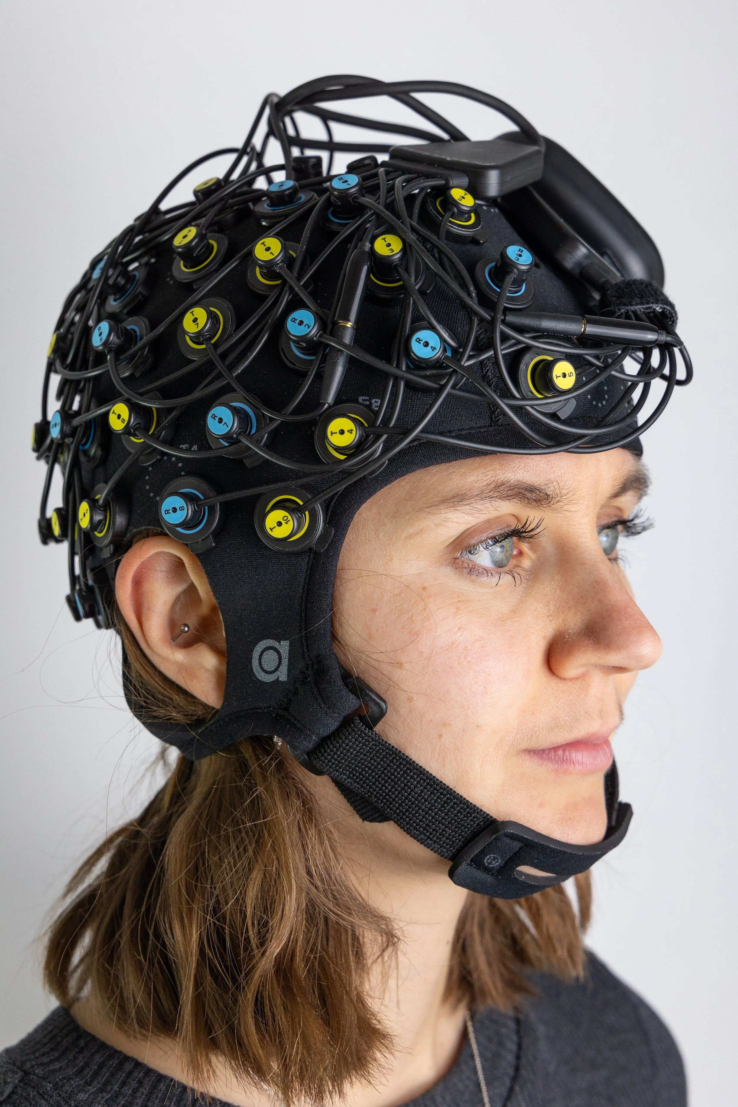
When positioning the optode template on the headcap, it is important to keep in mind the shift from a 2D view on paper to a 3D set-up on the headcap. Hence, the optodes that are in a straight line on paper do not always have to be on one height when setting up a template on the headcap. To illustrate, the 27-channel template shown in Figure 2 was set up on a headcap in Figure 4 to measure from the prefrontal cortex.
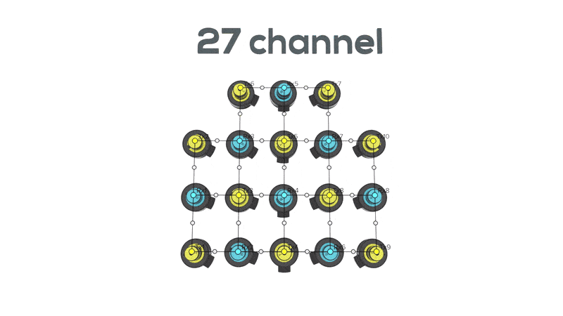

Figure 4: Optode template 27 channel applied on a headcap covering the prefrontal cortex (headcap size: M)

In case an optode template consists of multiple sub-templates, the sub-templates can be placed over different brain regions. Within the sub-template, the inter-optode distance and order of optodes should also be kept according to the template. Figure 5 shows application of the template in Figure 3 on the head to cover bilateral frontal and motor cortices.
Figure 5: Optode template 2x4 + 2x5 channel applied on a headcap covering bilateral frontal and motor cortices (headcap size: L)

What to do, if I cannot find a suitable optode template?
The optode templates provided in OxySoft cannot be modified by its users. If none of the available templates fits your regions of interest, you can purchase the Optode Template Editor software to design your custom template(s). Please note: only the Brite, BabyBrite, BriteLite, MediBrite and OxyMon can support customized templates.
For a detailed overview of how to use Optode Template Editor, follow this blog's step by step [link to come].
It is essential that the number of transmitters and receivers, as well as the inter-optode distance remain correct and constant throughout the entire template. If you encounter difficulties and would rather have one of our application specialists make the template for you, please reach out to us. After discussing which optode template layout you have in mind, we will be happy to provide you with a quote and help you out.
Any questions regarding optode templates left? Then feel free to reach out to us at askforinfo@artinis.com.


At Artinis, our mission is simple: make imaging easy, so researchers can focus on what matters, their research. Large-scale hyperscanning presented a clear challenge. We answered it the same way we always do: by removing the complexity and making it accessible.